
NAT (Network Address Translation) or more specifically PAT (Port Address Translation) is ubiquitous today - from a home Wi-Fi router to Internet access at large enterprises and sometimes even ISPs use a variant called CGNAT!
A quick note on terminology
Strictly speaking, in NAT only the IP addresses are modified, not the TCP/UDP port numbers; in PAT both IP address and L4 port numbers are modified to achieve better scale than NAT.
PAT is also sometimes called NAPT - Network Address and Port Translation.
In common usage the term NAT has expanded to cover PAT/NAPT as well - in this post we will use NAT as an umbrella term covering all variants.
Whether only the IP address is modified or both IP address and L4 port are modified, the concept remains the same.
What is NAT
NAT maps multiple private IP addresses within a home or organization to a single public IP address and vice versa - effectively hiding a network of devices behind a single IP address.
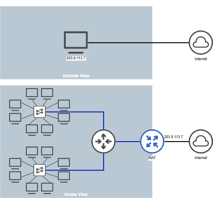
Consider an office with multiple computers - each of which needs a unique IP address. With IPv4 address being 32 bits, we can’t assign a globally unique IP address to each computer or device (with 128-bit IPv6 addresses - we can, but we might not want to!). So we assign private IP addresses within the organization. When any of the devices within the org needs to talk to another device on the Internet, it goes via NAT which converts the private IP to a public IP for outgoing packets and vice versa. A single public IP is shared and used for external communication amongst all the devices within the organization.
Other than the IPv4 scarcity reason, NAT also provides security and ease of management by separating the management scope of private IP addresses to the organization’s network team and the public IP assignment and management to the ISP.
How does NAT work
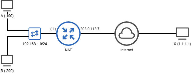
Consider two computers with IP addresses 192.168.1.100 and 192.168.1.200 within the organization. The public IP used by the organization, let’s say, is 203.0.113.7. The NAT is configured as the default gateway for both A and B. A simplified topology may be as follows -
When A (with a private IP) sends a packet towards X (having a public IP), here’s what happens -
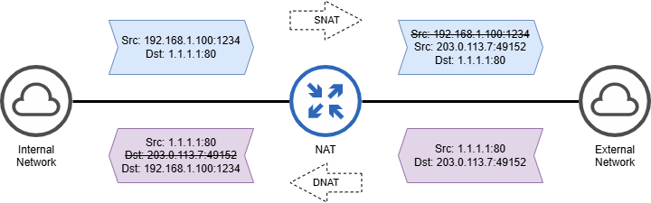
Agenerates packet with Source as192.168.1.100:1234and Destination as1.1.1.1:80- Packet reaches the NAT box (since it is the default gateway)
- NAT allocates a new source port, say
49152, and creates the following tracking entry in the NAT table
[Internal] 192.168.1.100:1234 <--> [External] 203.0.113.7:49152
- NAT modifies the source IP and source L4 Port in the packet. The destination IP and L4 Port is NOT modified. So, the (translated) packet that goes out of the NAT box towards X via the Internet has the following IP and Port Numbers -
Src 203.0.113.7:49152
Dst 1.1.1.1:80
This is called SNAT or Source Network Address translation and is performed for outgoing flows (internal to external).
Let’s see what happens with the reverse flow i.e. incoming flow -
Xsends a reply packet with Source as1.1.1.1:80and Destination as203.0.113.7:49152- When NAT receives this packet, it looks up the external IP/Port tuple in the NAT table matching the destination i.e.
203.0.113.7:49152 - The lookup results in the internal tuple
192.168.1.100:1234 - NAT modifies the destination IP/port in the packet to this internal tuple
- NAT sends packet on the internal network towards A with Source as
1.1.1.1:80(unmodified) and Destination as192.168.1.100:1234
This mapping of incoming flow is termed as DNAT or Destination Network Address Translation.
Note that the NAT translation is transparent to both A and X.
In practice, since you can have both TCP and UDP using the same port in parallel, NAT also stores and uses the packet’s IP protocol (TCP/UDP etc.) to lookup the mapping the in the NAT table.
How to verify NAT with Ostinato
Let’s start with the test topology. Your test topology and other test details will be different based on whether you are testing an individual NAT box in your lab or testing NAT in production.
Testing a NAT box in the lab
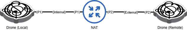
If you are testing a NAT box in the lab, you can connect both the internal and external ports to the same Ostinato/Drone instance as shown below -
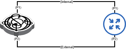
Using the same IP addresses as used in the example above, we assign IP addresses as follows -
- Drone Port P1 (Internal):
192.168.1.100/24 - Drone Port P2 (External):
1.1.1.1/24 - NAT Port P1 (Internal):
192.168.1.1/24 - NAT Port P2 (External):
1.1.1.100/24
Note that we don’t use the 203.0.113.7 IP address for the NAT external IP, because this is a reserved IP address for documentation and a non-routable address, so the NAT box will drop it.
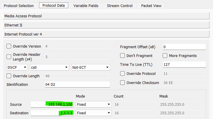
Create and configure a stream on Drone internal port P1 with the following attributes -
- Source IP:
192.168.1.100 - Destination IP:
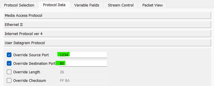
1.1.1.1 - IP protocol:
UDP - UDP Source Port:
1234 - UDP Destination Port:
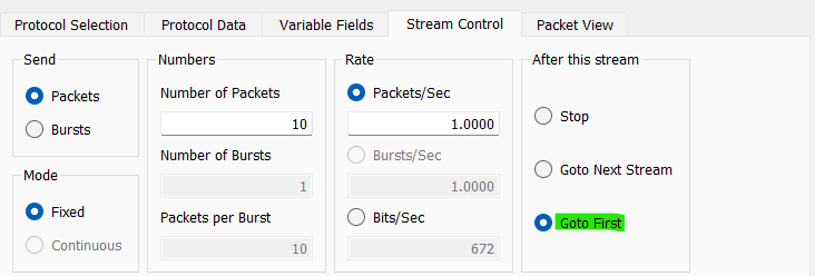
80 - Stream Control:
Goto First
Hit Apply and Start Transmit on Drone port P1. Verify packets are received on Drone port P2. Capture the packets on P2 and examine that the source IP and source UDP port has been modified in the packet which will verify that SNAT has been performed successfully on the outgoing flow.
Dump the NAT Table to verify the tracking entry has been created.
Before, we verify the reverse flow, write down the translated source UDP port as we will need it to configure the reverse flow.
To verify DNAT for the reverse flow, create and configure a stream on Drone external port P2 with the following attributes -
- Source IP:
1.1.1.1 - Destination IP:
1.1.1.100 - IP protocol:
UDP - UDP Source Port:
80 - UDP Destination Port: The translated UDP port from outgoing flow
- Stream Control/Next:
Goto First
Hit Apply and start Transmit on Drone port P2. Verify packets are received on Drone port P1. Capture the packets on P1 and examine that the destination IP and destination UDP port has been modified in the packet which indicates that DNAT has been successful.
We have verified NAT for flows in both directions!
Troubleshooting Tips
- Ensure that you send the outgoing flow first so that NAT populates the table for the incoming flow. If you send the incoming flow first, NAT will most likely drop the packet.
- If the incoming flow is not being forwarded by the NAT box, verify that the destination UDP port in the stream is same as the translated source port in the outgoing flow as captured on Drone port P2 and the NAT box has built a tracking entry in the NAT table correctly.
Testing NAT in production
If you are testing NAT in production, you will need to run two Drone agent instances - one local on the internal network and the other remote on the external network; both the drone instances can be managed via the same Ostinato GUI, ideally via an out of band management network.
The IP address assignments depend on your internal/external network configuration. You might find it convenient to write these down before you create test streams.
- Drone-Local Port P1 (Internal): local-p1
- NAT Port P1 (Internal): nat-p1
- NAT Port P2 (External): nat-p2
- Drone-Remote Port P1 (External): remote-p2
Create and configure a stream on Drone-Local port P1 with the following attributes -
- Source IP: local-p1
- Destination IP: remote-p2
- IP protocol:
UDP - UDP Source Port:
1234 - UDP Destination Port:
80 - Stream Control/Next:
Goto First
Hit Apply and Start Transmit on Drone-Local port P1. Verify packets are received on Drone-Remote port P2. Capture the packets on Drone-Remote P2 and examine that the source IP and source UDP port has been modified in the packet which will verify that SNAT has been performed successfully on the outgoing flow.
Dump the NAT Table to verify the tracking entry has been created.
Before, we verify the reverse flow, write down the translated source UDP port as we will need it to configure the reverse flow.
To verify DNAT for the reverse flow, create and configure a stream on Drone-Remote port P2 with the following attributes -
- Source IP: remote-p2
- Destination IP: nat-p2
- IP protocol:
UDP - UDP Source Port:
80 - UDP Destination Port: The translated UDP port from outgoing flow
- Stream Control/Next:
Goto First
Hit Apply and Start Transmit on Drone-Remote port P2. Verify packets are received on Drone-Local port P1. Capture the packets on P1 and examine that the destination IP and destination UDP port has been modified in the packet which indicates that DNAT has been successful.
We have verified NAT for flows in both directions!
To troubleshoot refer to the tips in the previous section.
To test multiple flows and NAT scaling, you need to generate multiple flows from Ostinato which we will cover in a future guides post.